Dual Fan Aerodynamic Lift Device
High-Efficiency VTOL Flight
High-Efficiency VTOL Flight
Over the last eight years this device was conceived, patented, prototyped and tested by William Gramling,retired engineer and veteran. The whole purpose of this device, which is not a ducted fan, is to offer an aerodynamic lift platform which, when one or more are fitted with an appropriate fuselage/cabin, creates an aircraft capable of VTOL flight.
Most importantly, it achieves this with the high efficiency of fixed-wing aircraft, normally three to five times higher than rotary wing aircraft, based on maximum takeoff weight. This combination offers viable, efficient and quiet, electrically-powered, and hybrid long-range commuter vehicles and commercial cargo carriers.
Most importantly, it achieves this with the high efficiency of fixed-wing aircraft, normally three to five times higher than rotary wing aircraft, based on maximum takeoff weight. This combination offers viable, efficient and quiet, electrically-powered, and hybrid long-range commuter vehicles and commercial cargo carriers.
Military
Military vehicles that are efficient, affordable and easily maintained are possible. They include heavy-lift and long-range troop and equipment carriers, quick and quiet automonous UAV’s with low-heat signatures for rescue and resupply. The lack of external rotors allows close-in support in urban and forested areas. Also, internal lift mechanisms are Kevlar-shieldable for improved battlefield survivability.
A preliminary quarter-speed test was conducted in September 2016 to observe airflow over the components and evaluate the relationship of air velocity and measurable lift. The results, 85 lb @ 50 ft/sec, exceeded expectations according to the lift equation.
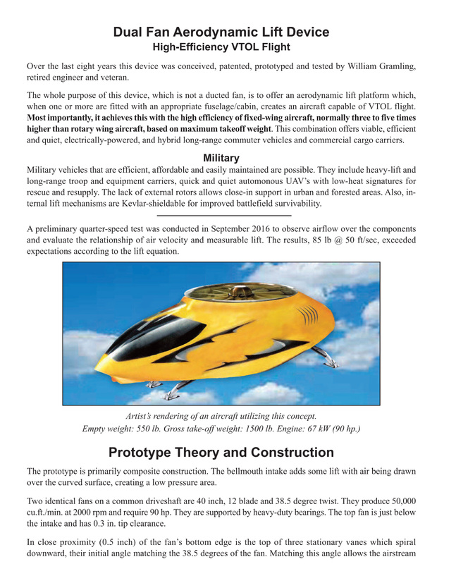
Artist’s rendering of an aircraft utilizing this concept.
Empty weight: 550 lb. Gross take-off weight: 1500 lb. Engine: 67 kW (90 hp.)
Empty weight: 550 lb. Gross take-off weight: 1500 lb. Engine: 67 kW (90 hp.)
Prototype Theory and Construction
The prototype is primarily composite construction. The bellmouth intake adds some lift with air being drawn over the curved surface, creating a low pressure area. Two identical fans on a common driveshaft are 40 inch, 12 blade and 38.5 degree twist. They produce 50,000 cu.ft./min. at 2000 rpm and require 90 hp. They are supported by heavy-duty bearings. The top fan is just below the intake and has 0.3 in. tip clearance.
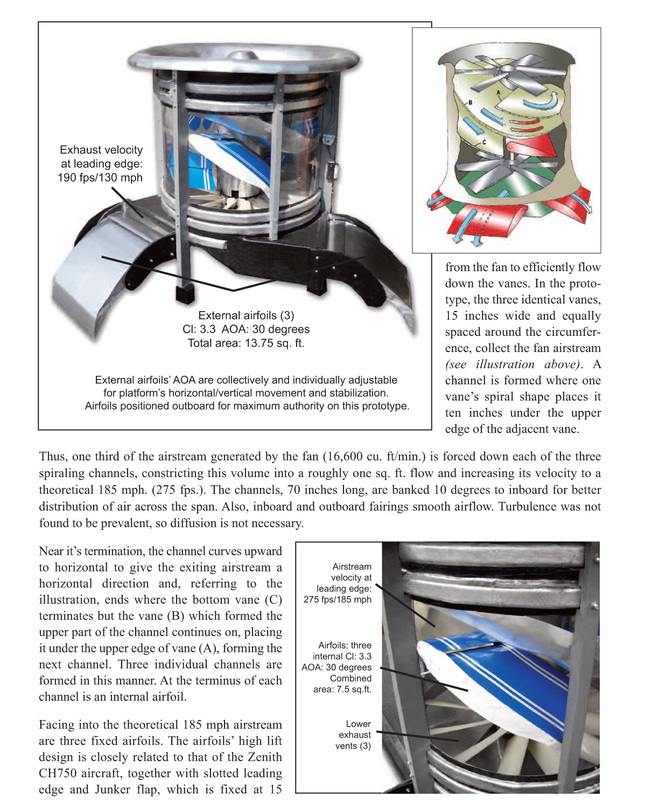
In close proximity (0.5 inch) of the fan’s bottom edge is the top of three stationary vanes which spiral downward, their initial angle matching the 38.5 degrees of the fan. Matching this angle allows the airstream from the fan to efficiently flow down the vanes.
In close proximity (0.5 inch) of the fan’s bottom edge is the top of three stationary vanes which spiral downward, their initial angle matching the 38.5 degrees of the fan. Matching this angle allows the airstream from the fan to efficiently flow down the vanes.
Thus, one third of the airstream generated by the fan (16,600 cu. ft/min.) is forced down each of the three spiraling channels, constricting this volume into a roughly one sq. ft. flow and increasing its velocity to a theoretical 185 mph. (275 fps.). The channels, 70 inches long, are banked 10 degrees to inboard for better distribution of air across the span. Also, inboard and outboard fairings smooth airflow. Turbulence was not found to be prevalent, so diffusion is not necessary.
Near it’s termination, the channel curves upward to horizontal to give the exiting airstream a horizontal direction and, referring to the illustration, ends where the bottom vane (C) terminates but the vane (B) which formed the upper part of the channel continues on, placing it under the upper edge of vane (A), forming the next channel. Three individual channels are formed in this manner. At the terminus of each channel is an internal airfoil. Facing into the theoretical 185 mph airstream are three fixed airfoils. The airfoils’ high lift design is closely related to that of the Zenith CH750 aircraft, together with slotted leading edge and Junker flap, which is fixed at 15 degrees.

Near it’s termination, the channel curves upward to horizontal to give the exiting airstream a horizontal direction and, referring to the illustration, ends where the bottom vane (C) terminates but the vane (B) which formed the upper part of the channel continues on, placing it under the upper edge of vane (A), forming the next channel. Three individual channels are formed in this manner. At the terminus of each channel is an internal airfoil. Facing into the theoretical 185 mph airstream are three fixed airfoils. The airfoils’ high lift design is closely related to that of the Zenith CH750 aircraft, together with slotted leading edge and Junker flap, which is fixed at 15 degrees. With a lift coefficient of 3.3, facing into the
airstream with an AOA of 30 degrees, the lift of each of the three is, according to the lift equation, very substantial. The total area of the three internal airfoils is 7.5 sq. ft. However, some losses from friction, turbulence and airstream manipulation may affect the result somewhat. The airfoils are also banked inboard by 10 degrees, and are twisted to outboard, making
the trailing edge horizonal.

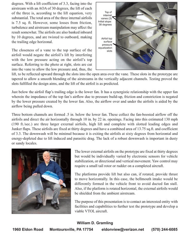
The closeness of a vane to the top surface of the airfoil would negate the airfoil’s lift by interfering with the low pressure acting on the airfoil’s top surface. Referring to the photo at right, slots are cut into the vane to allow the low pressure and, thus, the
lift, to be reflected upward through the slots into the open area over the vane. These slots in the prototype are tapered to allow a smooth blending of the airstreams in the vertically adjacent channels. Testing proved the slots fulfilled the design aims, and the lift of the airfoil is as predicted.
Just below the airfoil flap’s trailing edge is the lower fan. It has a synergistic relationship with the upper fan
wherein the impedance of the top fan’s airflow due to pressure build-up, friction and constriction is negated
by the lower pressure created by the lower fan. Also, the airflow over and under the airfoils is aided by the
airflow being pulled down.
Three bottom channels are formed .5 in. below the lower fan. These collect the fan-boosted airflow off the airfoils and direct the air horizontally through 10 in. by 22 in. openings. Facing into this estimated 130 mph (190 ft./sec.) are three larger external airfoils, high lift and complete with slotted leading edges and Junker flaps. These airfoils are fixed at thirty degrees and have a combined area of 13.75 sq.ft. and coefficient of 3.3. The downwash will be minimal because it is exiting the airfoils at sixty degrees from horizontal and energy-depleted due to lift induced and parasitic drag. The lack of a robust downwash is important in dusty or sandy locales.
The lower external airfoils on the prototype are fixed at thirty degrees but would be individually varied by electronic sensors for vehicle stabilization, or directional and vertical movement. Yaw control may require a small tail rotor or rudder on a completed aircraft.
The platforms provide lift but also can, if rotated, provide thrust to move horizontally. In this case, the bellmouth intake would be differently formed in the vehicle front to avoid ducted fan stall. Also, if the platform is rotated horizontal, the external airfoils would be shielded from the ambient airstream.
The purpose of this presentation is to contact an interested entity with facilities and capabilities to further test the prototype and develop a
viable VTOL aircraft.

William D. Gramling
1960 Eldon Road
Montoursville, PA 17754
eldonview@verizon.net
(570) 244-6085
1960 Eldon Road
Montoursville, PA 17754
eldonview@verizon.net
(570) 244-6085


